These locomotives run as MÁV M61 class in Hungary.
| Major dimensions | |
|---|---|
| Gauge | 1435 mm |
| Length over buffers | 18900 mm |
| Total wheel base | 14300 mm |
| Distance between bogie centres | 10300 mm |
| Bogie wheel base | 2000+2000 mm |
| Maximum height without supplies | 4280 mm |
| Maximum width | 3090 mm |
| Wheel diameter | 1040 mm |
| Weights | |
| Total weight in running order | 108660 kg |
| Adhesion weight | 108660 kg |
| Maximum axle load | 18110 kg |
| Operation data | |
| Maximum speed | 105 km/h |
| Maximum tractive effort at start | 292 kN |
| Continuous speed | 20 km/h |
| Continuous tractive effort (at 20 km/h) | 198 kN |
| Radius of minimum riding curve | 90 m |
| Supplies | |
| Fuel | 2700 litres |
| Lubricating oil tab | 760 litres |
| Cooling water | 920 litres |
| Water for train heating | 3000 litres |
| Sand | 525 kgs |
The main frame of the locomotive is settled on two three-axle bogies, through two-stage spring suspension system. The undreframe consists of 2 longitudinal I-bars connected by cross members, and are directly connected to the open-box-girder type buffer beams. The welded body of the locomotive which consists of the two cabins and the engine compartment, is welded to the underframe and forms a complete structure. This construction was widely known as "2-cab streamliner".
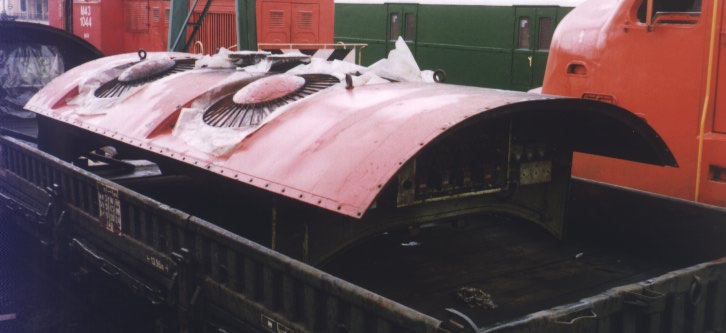
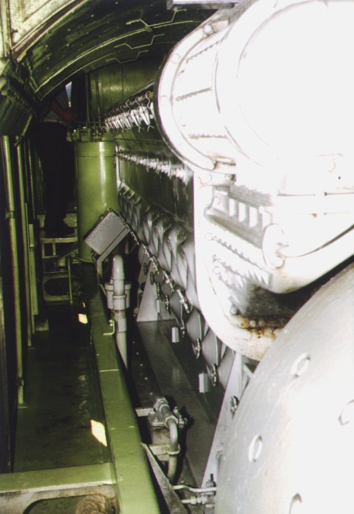
The hatches on the rounded roof of the locomotive provide access for the removal of the equipment. The side plates of the body is corrugated to increase the strength of the sides. The gangways in the engine room are provided with anti-skid plates welded to the underframe.
The bogie centre bearings are bolted to the bogie bolsters. The pilots are provided at each end of the main frame.
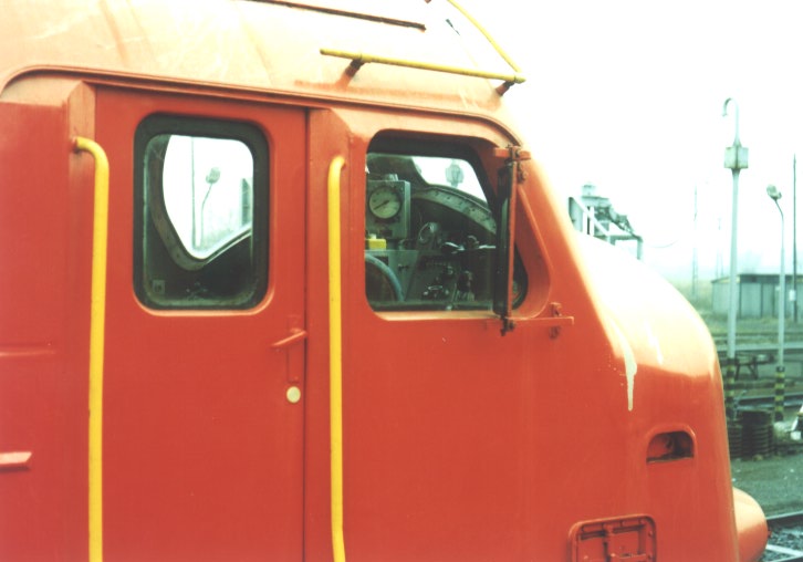
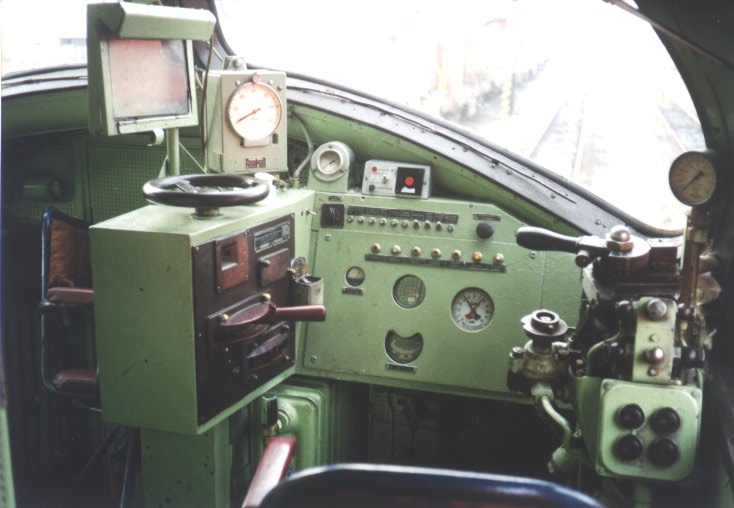
The control cab is an integral part of the body, is located ahead and above the locomotive floor. It provides a good view for the crew. The widely known "bulldog-nose" of the locomotive is designed for the protection of the crew. The windshields of the cab form a wide "V" to shed rain for a better visibility. All sashes are equipped with specially designed rubber strippings. Gutters are provided above the outside cab doors and the cab windows. All doors are hinged type. The cab is ventilated through the windows. The rear view mirrors are relatively large and adjustable.
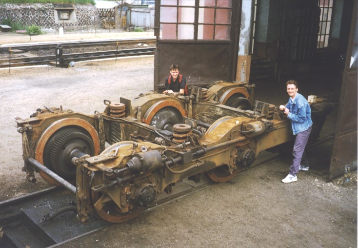
Bogies
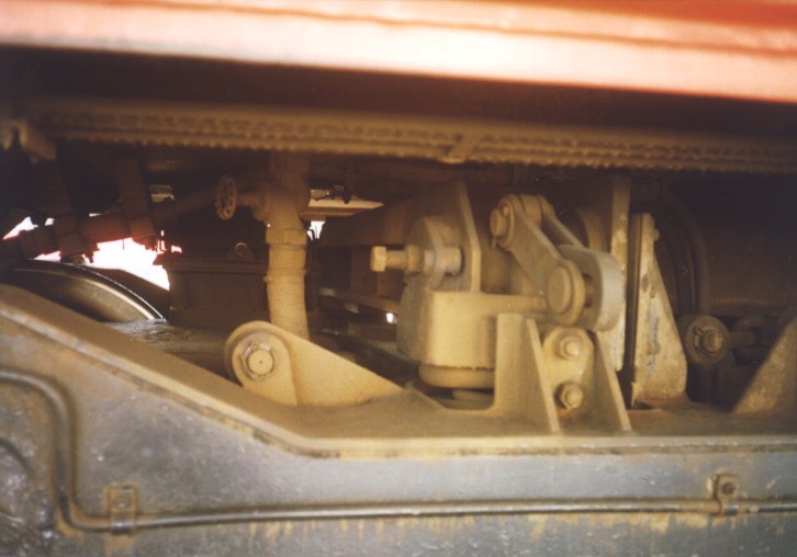
The bogies are interchangeable. The bogie frame and the bolster are of box type, welded construction. The bogie consists of two main bars connected with 2 bogie transoms. The axles are made of normal carbon steel. The wheels are made of forged and rolled steel and shrunk on the axles. The gears are pressed or shrunk on the axles. The journal boxes are placed outside the wheels and equipped with roller bearings permitting the lateral movement of the journal. The traction motors are geared directly to axles and carried in a conventional manner between the axles and the bogie transoms with a multiple coil spring suspension on the transom.
The two-stage spring system provides a full flexibility for the bogie. Two double-coil springs are on the top of each journal box. Four double-coil springs connecting the frame and the bolster, also act as pendulums.
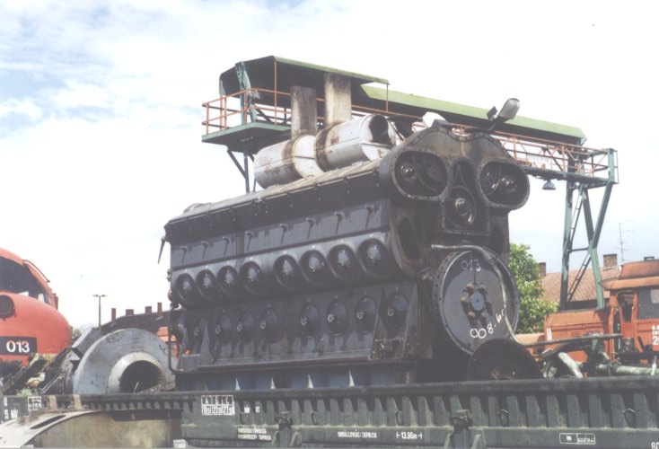
Engine
The power plant of the locomotive is a GM-EMD 16-567D1 type Diesel, 16-cylinder, two-stroke, V-form engine.
| Main data: | |
|---|---|
| Nominal output | 1435 kW (1950 HP) |
| Output on test pad | 1620 kW (2200 HP) |
| Bore | 8 1/2 " (216 mm) |
| Stroke | 10"(254 mm) |
| Capacity | 9072 cubic inches
(148,663 litres) |
| Idle speed | 275 RPM |
| Nominal speed | 835 RPM |
| Overspeed protection turns on at | 910 RPM |
| Cooling-water temperature | 77...83 C |
| Effective mid-pressure | 7,07 bar |
| Injection pressure | 130...150 bar |
The cooling system consists of 2 direct driven centrifugal water pumps built on the governor side of the engine, two radiators and four AC motor-driven cooling fans built in the hatch above the engine. The four fans turn on at the cooling water temperature values of 74, 76, 78, 82 C, respectively. The shutters of the cooling system are settled in the walls under the fans, and operated by an electropneumatic valve. The water-cooled lubricating oil cooler is settled on the governor end of the engine. A full ceiling with removable units separates cooling air and engine room air. The cooling water tank is built on the governor end of the engine. The tank is built so that the water can flow back into the engine in service pause and keeps the engine warm. Automatic water temperature control and hot engine alarm is provided.
The lubricating system contains three gear-driven pumps (two lubricating all bearings, rods, cams, pistons and the scavenging pump provides cooled and filtered oil for the system), fine and coarse oil filters built at the governor side, and low oil pressure control.
The fuel system contains a return flow DC motor driven gear pump protected by suction filter in addition to discharge filters to ensure clean fuel for the engine. A combination of sight glasses and relief valves offer visual indication of any system trle. Two rounded fuel tanks are provided under the engine on the two sides of the locomotive with filling stations on each sides and flame arrestors in the engine room. The fuel level is visible form outside by a fuel gauge.
The engine can be started and turn off by pressing the start or turn off switch on the control panel situated in the engine room, at the governor end of the engine. The start process uses the main generator as a DC motor supplied from the storage battery.
Transmission and auxiliaries
The locomotive is built with a 600 V DC transmission and a 2-way type auxiliary system.
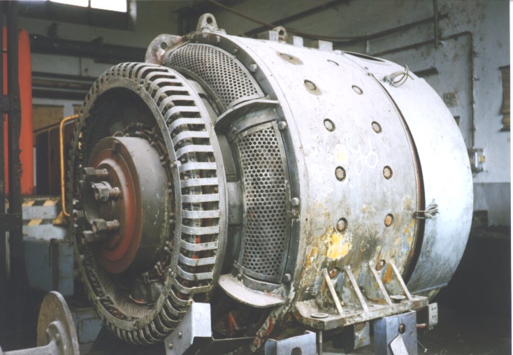
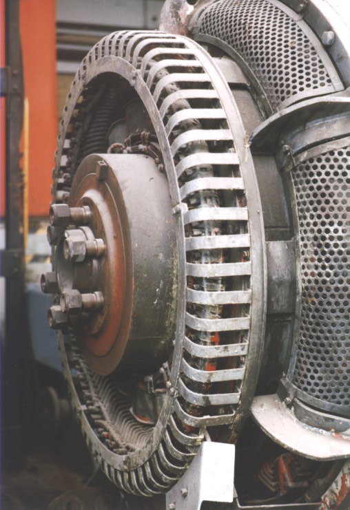
The main generator is a GM D22 type 12 pole, nominally 600 V DC with forced ventilation, single bearing and directly connected to the crankshaft on the other end by a flexible coupling. The capacity is suitable to transmit the rated output of the engine continuously to the traction motors.
The alternator is a GM D-14 type AC generator, 3 phase, 16 pole and integral with the main generator. It serves to supply AC for the 4 engine cooling fan motors and the 6 traction motor blower motors. Its output is 100
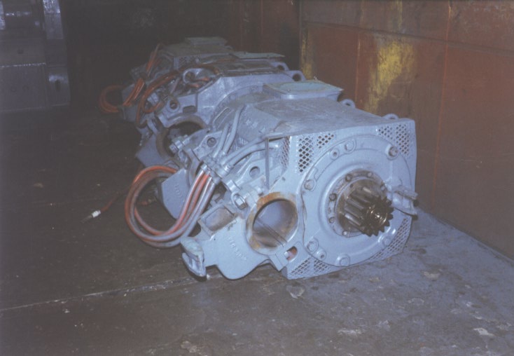
The traction motors are GM D47 type , 4-pole motors, each cooled by individual, AC motor-driven cooling fans through flexible rubber ducts between the motor and the underframe opening. At lower speed, two motors are series wound, and three such circuits are paralleled; above 20 km/h three motors are series wound forming 2 paralleled circuits. This system is constructed to provide larger tractive effort at lower speeds.
The constant voltage, automatically regulated auxiliary generator is a GM A-8102 A type, 74 V DC generator. Output: 18 kW. Supplies the control circuits, lighting and battery charging. The battery is a 64 V 284 Ah, alkaline type, and situated in two cabinets underneath the main generator, accessible for servicing form outside. It is charged by the auxiliary generator, but it can also be charged from outside.
The control cabinet is situated at the end of the engine room, on the side of the main generator. It houses the high and low voltage control equipment of all electric systems. The driver's control station is located on the right side of the cab. It contains the speed control throttle, the reverse lever on its left side and the air brake handles (Knorr type) on its right side. The output of the engine is divided into 8 stages, where the engine speeds and the outputs are the following:
| Stage | Engine speed (rpm) | Engine output (kW) |
|---|---|---|
| 1 | 275 | 96 |
| 2 | 330 | 220 |
| 3 | 455 | 390 |
| 4 | 500 | 580 |
| 5 | 630 | 783 |
| 6 | 685 | 995 |
| 7 | 760 | 1215 |
| 8 | 835 | 1435 |
The local control station can be found in the engine room, on the governor end of the engine. It contains the start and stop buttons, the isolation switch, the oil and water pressure gauges, the fuel pump switch, and the master relay of the throttle. The engine can be started by pressing the start button and can only be loaded if the isolation switch is on.
Air system, brakes and sanding
A direct driven, Atlas Copco CT 4 type air compressor is located in the engine room, under the water reservoir. Its capacity is 4800 litres/min (1600 litres/min in idling), at 9 bar pressure. The two main reservoirs of the capacity of 700 litres each are situated under the engine, between the fuel tanks. The compressed air is cooled by coils between the compressor and the first reservoir.
The brake equipment is of Knorr type, automatic for both the locomotive and the train and independent for the locomotive alone. The brake cylinders are arranged on the bogie frames. The brake piping is of stainless steel. The braking percentage, expressed as percentage of the adhesion weight with all tanks filled is at least 144% at 100 km/h (and over) and 75% at speeds below 100 km/h. Brake shoes are provided on all wheels in a clasp brake arrangement. One wheel pair is provided with hand brake for parking.
The wheel slip control initiates sanding automatically in either direction of operation. A manual forward/reverse sanding is also supplied.
Train heating
A Vapor-Clarkson OK 4616 type automatic oil-heated steam generator of 800 kg/hour is located in the engine room between the engine auxiliaries and the "A" driver's cab. The water tank of 3000 litres capacity is located in the engine room between the main generator and the control cabinet and can be replaced by a fuel tank if necessary.
Equipment
Adjustable sun visors on each sides on the cab, diaphragm type air horns, pneumatic windshield wipers for all windshields, carbon dioxide type fire extinguishers (two in cabs, one in engine room), one headlight and two buffer lamps are provided.
In each cab, one fixed, upholstered, sliding seat with forward-backward-height adjustment possibility and an additional seat for the helper is provided.
One turning jack for engine timing and inspection for one man operation is added to the equipment.
Words by Peter Werner Groh
Gigant Club NOHAB Division